Mioverse™ Architecture

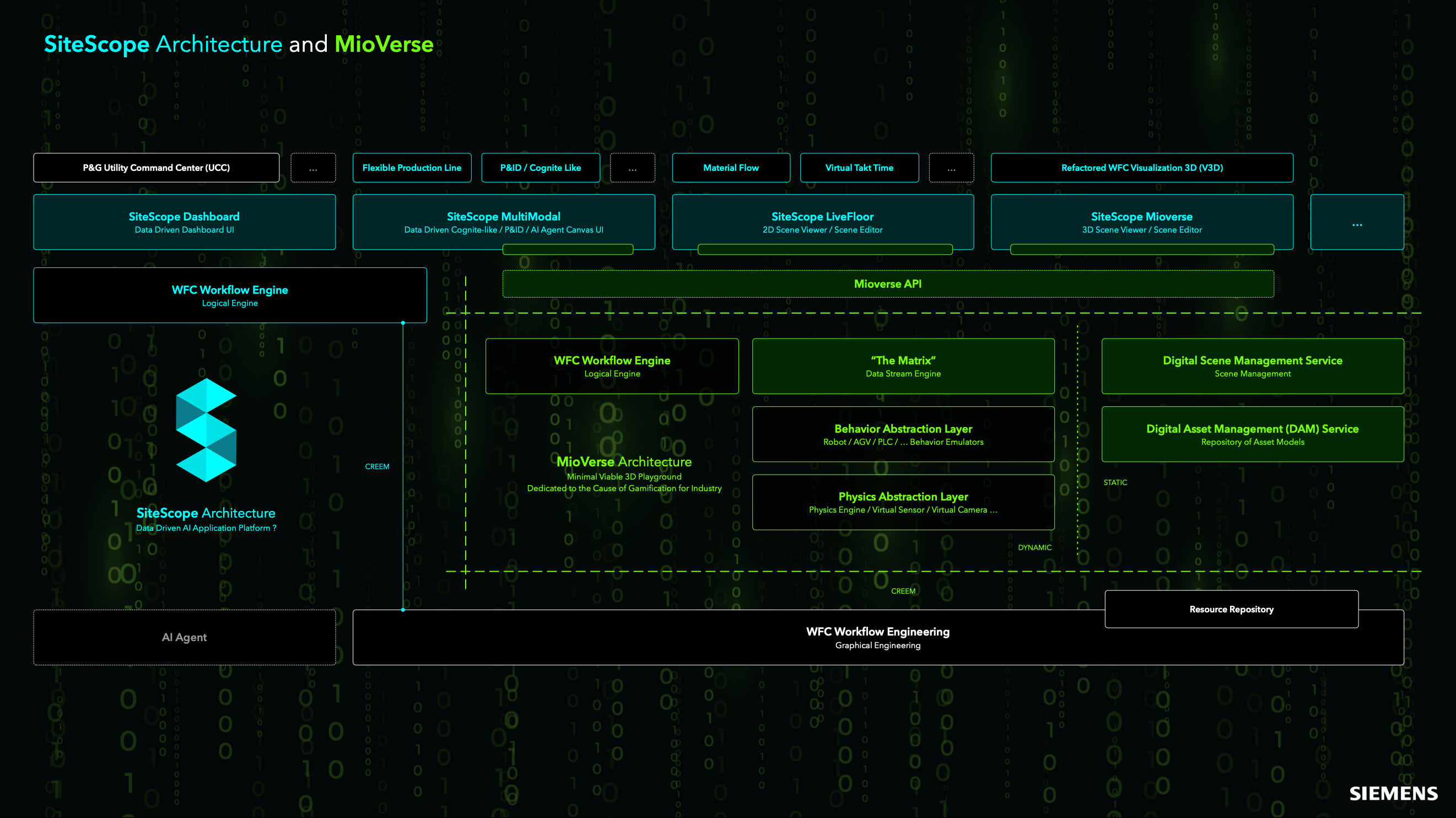
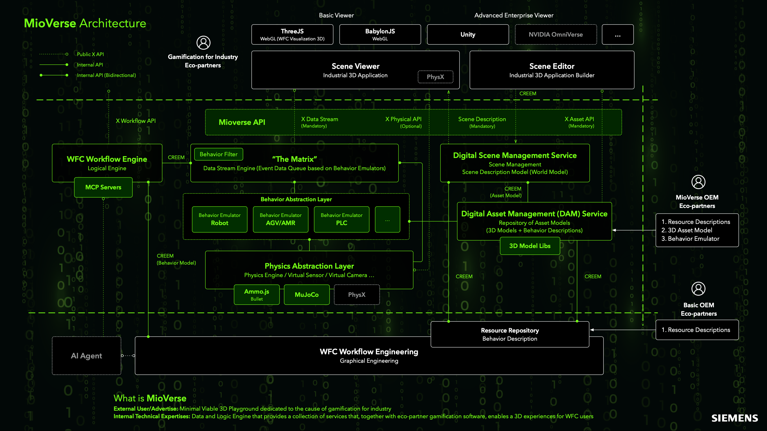
The diagram illustrates the MioVerse Architecture as a layered, service-oriented industrial 3D platform that integrates visualization, simulation, data streaming, and IT/OT workflow orchestration into a unified digital environment.

At the top layer, MioVerse supports multiple scene viewers and scene editors, ranging from web-based viewers such as Three.js and BabylonJS to advanced enterprise-grade platforms including Unity and NVIDIA Omniverse. These viewers consume standardized scene descriptions, asset definitions, and data streams to render and interact with industrial 3D applications.

The core integration layer is exposed through the MioVerse API, which provides mandatory interfaces for data streaming, scene description, and asset management, as well as optional physical APIs. This API layer decouples visualization clients from the underlying execution, data, and simulation services, enabling extensibility and ecosystem participation.

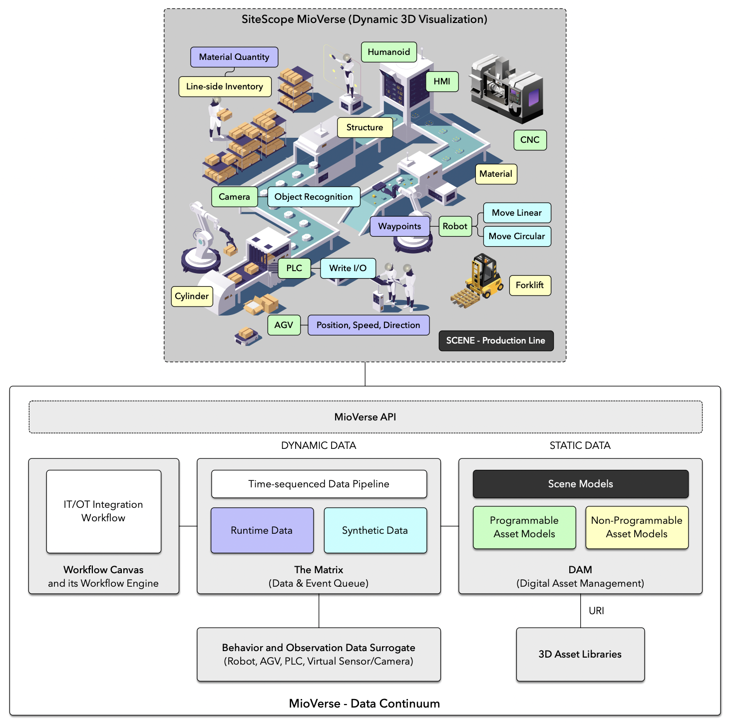
Dynamic behavior and event data are managed by "The Matrix", a centralized data stream engine that functions as an event-driven queue based on behavior emulators. It aggregates runtime signals produced by robots, AGVs/AMRs, PLCs, and other industrial entities through a dedicated behavior abstraction layer, ensuring consistent temporal sequencing and semantic alignment.

Beneath this layer, the physics abstraction layer integrates multiple physics engines and virtual sensing technologies, such as Ammo.js, MuJoCo, and PhysX, to support realistic motion, collision, and perception modeling. This allows physical behaviors and virtual sensors or cameras to be treated as first-class data sources.

Static and semi-static knowledge is governed by the Digital Scene Management Service and the Digital Asset Management (DAM) Service. These services maintain world models, scene descriptions, asset models, and associated 3D model libraries, linking structural definitions with reusable behavior descriptions via standardized resource identifiers.

On the orchestration side, the WFC Workflow Engine provides a logical execution environment for IT/OT integration workflows, while WFC Workflow Engineering enables graphical authoring and lifecycle management of behaviors and control logic. This layer also supports AI agents, enabling autonomous reasoning and interaction with industrial scenes.

Collectively, the MioVerse architecture establishes a scalable industrial metaverse foundation in which visualization, physics-based simulation, real-time data streams, and workflow-driven logic converge. This design enables ecosystem collaboration, digital twin realization, and gamified industrial experiences across both internal and partner-driven solutions.

SiteScope for Mioverse™ Architecture
MioVerse - Data Continuum

The figure presents the overall architecture of MioVerse - Data Continuum, a data-driven industrial digital environment that integrates dynamic 3D visualization with an underlying IT/OT data continuum.

At the top layer, SiteScope MioVerse (Dynamic 3D Visualization) represents a production-line scene composed of heterogeneous industrial assets, including robots, CNC machines, PLC-controlled devices, AGVs, forklifts, cameras, HMIs, and humanoid operators. These assets are modeled not only geometrically but also semantically, exposing properties such as structure, material, inventory, waypoints, motion primitives (e.g., linear and circular movement), and operational states. The scene serves as a unified spatial and semantic context in which real-time behaviors—such as robot motion, AGV navigation, PLC I/O, sensor perception, and object recognition—are visualized and analyzed.

The visualization layer is decoupled from data generation and orchestration through the MioVerse API, which bridges the scene with the underlying data infrastructure. Below this interface, the architecture distinguishes between dynamic data and static data.

Dynamic data is managed by a time-sequenced data pipeline, referred to as The Matrix, which functions as a unified data and event queue. It aggregates both runtime data sourced from physical systems and synthetic data generated by simulations or virtual sensors. This design enables temporal alignment, event-driven processing, and consistent replay or augmentation of industrial behaviors.

Static data is managed through a Digital Asset Management (DAM) subsystem, which maintains scene models and asset models. These include both programmable assets (e.g., robots, PLCs, AGVs) and non-programmable assets (e.g., passive structures, materials), each referenced via URIs and linked to reusable 3D asset libraries. This separation ensures that structural and semantic definitions remain stable while behaviors evolve dynamically at runtime.

On the orchestration side, an IT/OT Integration Workflow, implemented via the Workflow Canvas and its workflow engine, coordinates data flows, control logic, and system interactions across enterprise IT systems and operational technology.

At the lowest layer, behavior and observation data surrogates abstract physical and virtual entities—such as robots, AGVs, PLCs, and virtual sensors—providing a consistent interface for data acquisition, simulation, and control.

Collectively, the architecture realizes a MioVerse Data Continuum in which static asset knowledge, real-time operational data, and synthetic behavioral data are integrated into a coherent and extensible digital environment. This enables scalable digital twins, closed-loop simulation, and advanced analytics for complex industrial production systems.

Steps
  • CAD preprocessing: segmentation and simplification
  • Import CAD building blocks individually into Mioverse DAM
  • Open SiteScope Mioverse, connect to DAM library, drag building blocks to assemble the scene
  • [Animation Script] e.g., automated storage, door open/close stored in DAM
  • WFC: build resource tree
  • In SiteScope Mioverse, bind 3D blocks to resources
  • [V3D->Matrix] Robot forward/inverse kinematics compute path points
  • [V3D->Matrix] AGV path simulation
  • [V3D->Matrix] PLC LUT or I/O triggers
  • WFC: write workflow
  • Joint debugging